What Is a Drilled Shaft Foundation? A Technical Guide for Infrastructure Projects
By Sadler Electric, Inc. — Omaha & Council Bluffs Traffic Signal and Infrastructure Contractors
Drilled shaft foundations are one of the most reliable deep foundation systems used in transportation and civil infrastructure projects across North America. A drilled shaft is a cast-in-place concrete foundation element constructed by drilling a cylindrical hole into the earth or rock, placing a reinforcing steel cage inside, and filling the hole with structural concrete. The result is a continuous, monolithic column of reinforced concrete that transfers structural loads directly into stable soil or bedrock far below the surface.
In the transportation sector — traffic signals, highway lighting, overhead sign structures, mast arms, and bridge substructure — drilled shafts are the standard foundation method. They are also called drilled piers, bored piles, or caissons, depending on the region and the agency specification. In Nebraska and Iowa DOT practice, "drilled shaft" is the preferred term and refers specifically to the cast-in-place deep foundation defined in AASHTO LRFD Bridge Design Specifications Section 10.8.
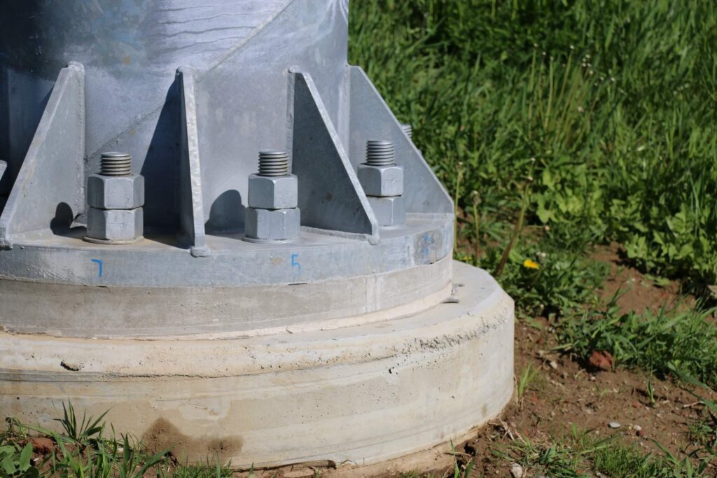
What Makes a Drilled Shaft Different From a Driven Pile
The distinction matters for project selection, equipment requirements, and site conditions.
A driven pile is a pre-manufactured steel, concrete, or timber member that is hammered, vibrated, or pushed into the ground from above. A drilled shaft is formed in place: the hole is excavated first, steel is lowered in, and concrete is poured around it.
Driven piles generate significant noise and vibration — sometimes enough to disrupt adjacent utilities, structures, or finished pavement. Drilled shafts are relatively quiet and low-vibration, which is why they are preferred in urban environments, near existing pavement, and alongside sensitive structures like bridge abutments or existing traffic control equipment.
Drilled shafts can be constructed to much larger diameters and depths than driven piles of comparable cross-section. Typical diameters for transportation applications in Nebraska and Iowa range from 18 inches (for small sign structures and single-arm signal poles) to 36 inches or more for large mast arm intersections and overhead sign bridges. Depths depend on soil profile and load requirements, commonly 10 to 25 feet for signal and light pole foundations and 30 to 60 feet or more for bridge and retaining structure elements.
Construction Sequence for a Drilled Shaft
Understanding the sequence clarifies why this work requires specialty contractors and close inspection.
Step 1 — Layout and utility clearance. Before any drilling begins, the shaft location is staked by a licensed surveyor and the utility clearance process is completed. Drilled shaft equipment operates large augers or rotary heads that can destroy an unmarked gas line or fiber conduit within seconds of contact. The approved plans and agency specifications control the allowable plan-position tolerance.
Step 2 — Drilling the hole. A crane-mounted or truck-mounted drill rig advances a flight auger or bucket auger into the ground. In cohesive soils (clays and dense silts common in Douglas, Sarpy, and Pottawattamie Counties), the borehole may stand open without support. In granular or groundwater-affected soils, temporary casing is advanced ahead of drilling to maintain borehole stability. In bedrock, a core barrel or rock auger is substituted.
Step 3 — Inspection of the borehole. Before concrete placement, the base of the hole is inspected for cuttings, slurry, and soft material. For DOT projects, a geotechnical inspector typically measures the cleanliness of the base to agency specification. Loose material at the bottom of a drilled shaft reduces tip resistance and must be removed.
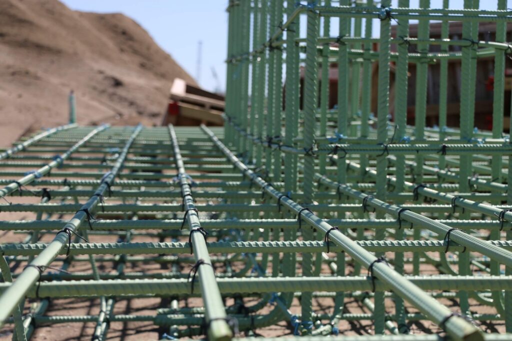
Step 4 — Reinforcing steel cage placement. The rebar cage is fabricated to the engineer's design, which specifies bar size, spacing, lap length, spiral ties or hoops, and top of reinforcement elevation. The cage is lowered into the hole and blocked off the bottom to maintain the specified concrete cover. Concrete cover is the value shown in the approved reinforcement details and applicable project specification.
Step 5 — Concrete placement. Concrete is placed through a tremie pipe or pump from the bottom up if water or slurry is present, or poured directly from a truck if the hole is dry. Concrete strength, slump, air, placement method, and testing requirements are set by the approved mix design and project specifications. Slump and air content are tested as required by the approved mix design and project specification.
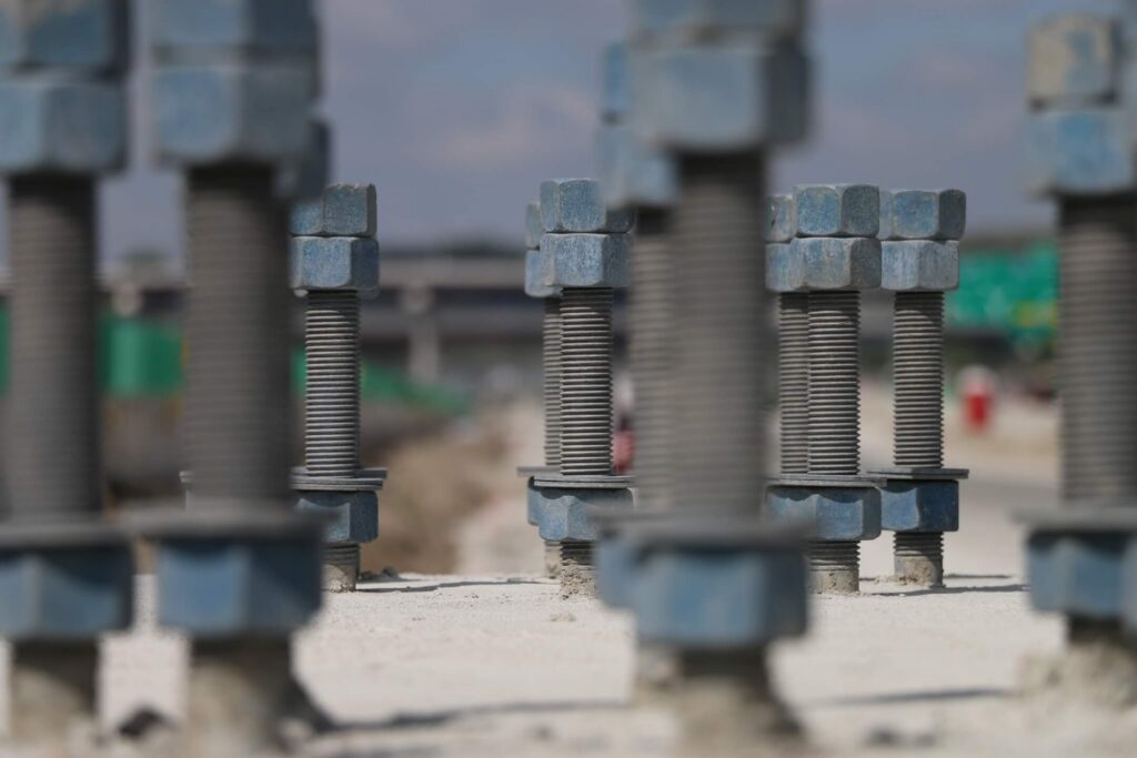
Step 6 — Curing and testing. After placement, the shaft is allowed to cure before the pole anchor bolts are set or the column form is placed. For large structural shafts on DOT bridge projects, integrity testing using Crosshole Sonic Logging (CSL) or Thermal Integrity Profiling (TIP) may be required to verify concrete quality through the full depth.
Load Transfer Mechanisms in Drilled Shafts
A drilled shaft resists load through two paths: side friction (also called skin friction) along the shaft perimeter, and end bearing at the shaft tip. The relative contribution of each depends on soil type, shaft geometry, and whether the tip is founded in rock, dense sand, or hard clay.
In Nebraska's loess-dominated soil profile, side friction often contributes significantly to total capacity because the loess is dense and cohesive. In Iowa's alluvial soils along the Missouri River corridor, groundwater and soft interbedded layers can limit skin friction, making depth-to-bearing stratum and tip condition more important.
For signal and lighting poles, the dominant load condition is lateral load from wind — not axial compression. The shaft must resist the overturning moment from wind acting on the pole and luminaire or signal heads. This is why signal pole shafts are often deeper relative to their diameter than pure compression shafts: depth provides the moment resistance arm.
Why Specialty Contractors Perform This Work in Omaha and Council Bluffs
Drilled shaft construction for transportation infrastructure in Nebraska and Iowa is performed by specialty contractors who work directly with state DOT agencies. The work requires dedicated drill rig equipment, trained operators, knowledge of local soil and groundwater conditions, and familiarity with DOT inspection and documentation requirements.
Sadler Electric, Inc., based in Ralston, Nebraska, has been completing drilled shaft foundations for Iowa DOT (IADOT) and Nebraska DOT (NEDOT) for over 35 years, including thousands of shafts. Whether experience documentation and a project-specific drilled shaft installation plan are required, and in what form, is set by the bid documents for the individual project. Check the applicable NDOT or Iowa DOT contract. Sadler Electric performs this work for traffic signal poles, mast arms, roadway lighting structures, and highway sign supports throughout the Omaha and Council Bluffs metro area, working with Nebraska DOT, Iowa DOT, municipalities, and general contractors across Douglas, Sarpy, and Pottawattamie Counties.
For project inquiries in Omaha, Council Bluffs, or the surrounding 50-mile service area, contact Sadler Electric at (402) 331-3217 or through the contact form at sadlerelectric.com.
This article is intended as general technical information about drilled shaft foundations in transportation infrastructure applications. Site-specific conditions always govern; consult a licensed geotechnical engineer for project-specific foundation design.
Planning a Drilled Shaft Project?
Sadler Electric installs drilled shaft foundations in the Omaha and Council Bluffs area. Call (402) 331-3217 or send us a message to talk through your project.