Drilled Shaft Foundations: The Complete Guide to Installation, Capacity, and Cost
By Sadler Electric, Inc. — Omaha & Council Bluffs Infrastructure Contractors
Drilled shaft foundations are the standard deep foundation method for transportation infrastructure across Nebraska and Iowa. Traffic signal poles, mast arms, roadway lighting structures, overhead sign bridges, and highway signing supports all rely on drilled shafts to stand up to wind, vehicle impact loads, and the seasonal freeze-thaw cycles that move the surface soils around them.
What Is a Drilled Shaft Foundation?
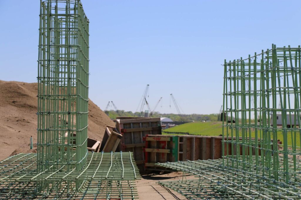
A drilled shaft foundation is a cast-in-place deep foundation element. A drill rig bores a cylindrical hole into the earth, a reinforcing steel cage is lowered into the hole, and structural concrete is placed to fill it. The finished product is a continuous column of reinforced concrete that transfers the structural loads from the pole or structure above it directly into stable soil or bedrock far below the surface.
Drilled shafts go by several names depending on the region and the agency. In Nebraska and Iowa DOT practice, "drilled shaft" is the standard term and refers specifically to the cast-in-place deep foundation defined in AASHTO LRFD Bridge Design Specifications Section 10.8. In other contexts you may hear them called drilled piers, bored piles, or caissons — these names describe the same or closely related construction method.
What distinguishes a drilled shaft from other deep foundation types is that it is formed in place at the project location rather than being manufactured off-site and installed. This makes it highly adaptable to site conditions, load requirements, and space constraints.
Drilled Shaft Diameter and Depth
For transportation signal and lighting infrastructure in Nebraska and Iowa, the design dimensions are determined by the structural engineer responsible for the pole or sign design.
Typical diameters for signal and lighting work:
- Small sign structures, single-arm signal poles: 18 to 24 inches
- Standard mast arm poles at signalized intersections: 24 to 36 inches
- Large or long-span mast arm poles, dual-mast arms: 36 to 48 inches
- Overhead sign bridges: 48 to 72 inches or larger
Typical depths:
- Signal and light pole shafts in Omaha loess soils: 10 to 20 feet
- Large mast arm shafts under high wind loading: 18 to 30 feet
- Bridge substructure elements: 30 to 60+ feet
Depth is driven primarily by the lateral load (wind moment), not by axial load. A signal pole shaft must resist the overturning moment from wind acting on the pole, mast arm, and signal heads. Deeper embedment provides more soil reaction to that moment. The geotechnical engineer determines the minimum depth and diameter from an analysis of the soil profile and the structural loads.
Drilled Shaft Installation Equipment
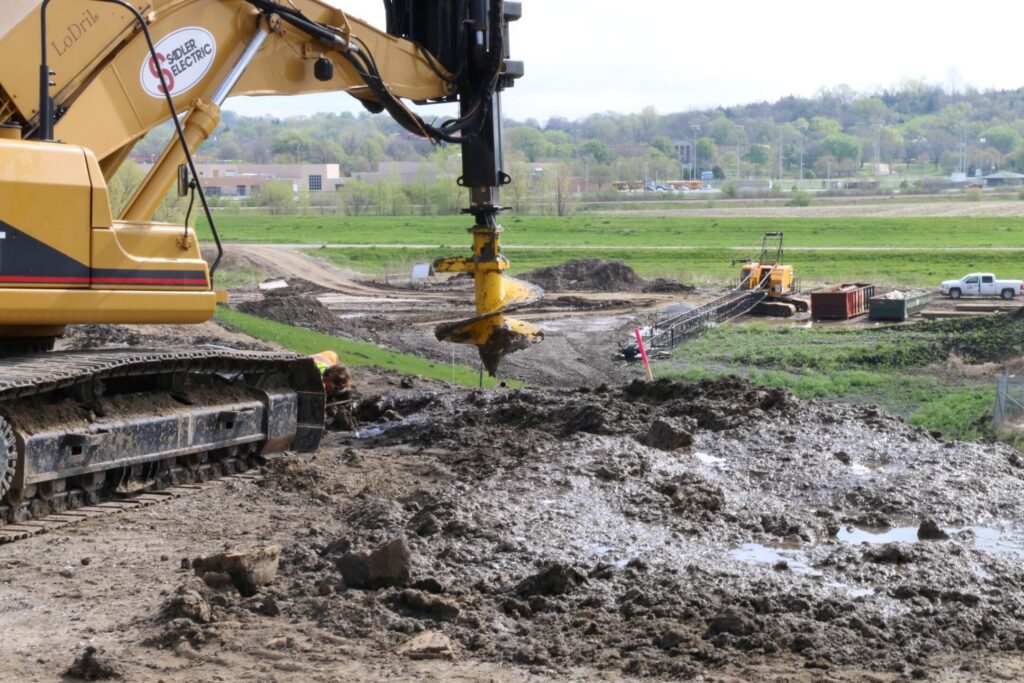
Drilled shaft construction requires specialized equipment sized to the shaft dimensions and site conditions. Sadler Electric operates a fleet of five drill rigs manufactured by Bay Shore Systems, ranging from the LAD140 for limited-access locations and smaller-diameter shafts to the TR-60 for large production work and large-diameter shafts. Support equipment includes cranes, telehandlers, excavators, skidsteers, slurry tanks, and mixing equipment.
The primary tool is the rotary drill rig, which advances either a flight auger (for cohesive soils) or a bucket auger (for granular soils) to the required depth. In the cohesive loess soils that dominate the Omaha metro, the borehole typically stands open without casing in the upper section. In granular soils or where groundwater is shallow, a temporary steel casing is advanced ahead of the auger to maintain borehole stability.
Urban intersection work favors compact equipment that can operate within a single closed lane. The drill rigs used for signal and light pole shaft work are purpose-built for tight urban sites — a significant factor in a dense metro environment like Omaha and Council Bluffs where the work happens at busy intersections surrounded by existing utilities and pavement.
Whether a project-specific drilled shaft installation plan is required, and what it must set out about equipment, methods and sequence, is stated in that project's contract documents.
Construction Sequence Step by Step
The construction sequence for a drilled shaft follows the same general steps across Nebraska DOT, Iowa DOT, and local municipal projects.
Step 1 — Survey layout and utility clearance. The shaft location is staked by a licensed surveyor before any drilling begins. Set out the shaft to the tolerance shown in the approved plans and applicable agency specifications. Utility clearance — a mandatory mark-and-locate process — identifies existing gas, electric, telecom, and fiber in the drill path.
Step 2 — Equipment setup and traffic control. The drill rig is positioned and traffic control is established per the approved Traffic Control Plan. Depending on the road classification, this may involve full or partial lane closure with flaggers, portable signals, or a permitted lane closure.
Step 3 — Drilling the shaft. The drill rig advances a flight auger or bucket auger into the ground. Shafts can be constructed using dry, wet, or cased methods — both temporary and permanent casing — depending on soil and groundwater conditions. In occasional cobble or cemented layers, specialized tooling is substituted.
Step 4 — Borehole inspection. Before any reinforcing steel or concrete goes in, the borehole is inspected. A geotechnical inspector measures the cleanliness of the base, checks for cuttings or slurry accumulation, measures borehole diameter, and confirms the borehole meets specification.
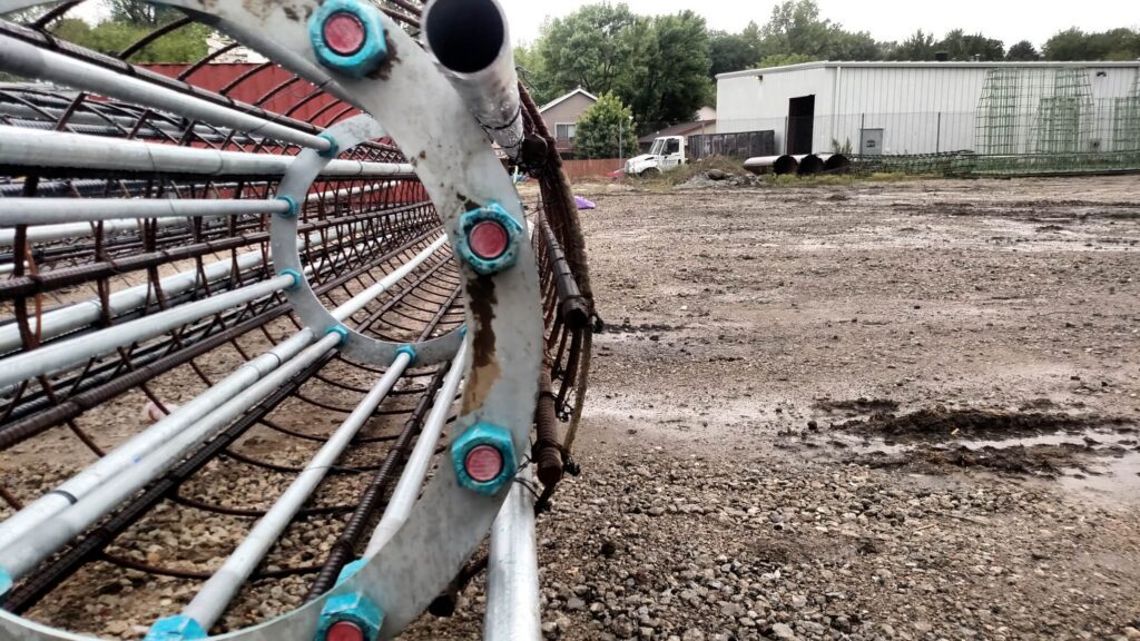
Step 5 — Reinforcing steel cage placement. The rebar cage is fabricated to the engineer's design. Use spacers and supports to maintain the concrete cover shown in the approved reinforcement details and project specifications.
Step 6 — Anchor bolt template setting. For signal poles and mast arms, anchor bolts must be set to the precise elevation, diameter, and angular orientation specified on the pole shop drawings. The template is positioned at the top of the borehole before concrete placement and held in position during pour.
Step 7 — Concrete placement. If the hole is dry, concrete is placed directly from the truck chute or a pump line. If water or slurry is present, concrete must be placed through a tremie pipe from the bottom upward to prevent segregation. The required concrete strength is the value in the approved mix design and contract documents.
Step 8 — Curing and documentation. The shaft is left to cure under protection as required by the specification. The contractor documents the as-built depth, diameter, concrete volume placed, and results of inspection for the project record. Some DOT contracts require a drilled-shaft installation plan, experience documentation, or both. Check the project’s special provisions and prequalification documents.
Drilled Shaft Work in Omaha and Council Bluffs
Sadler Electric, Inc., based in Ralston, Nebraska, has been completing drilled shaft foundations for Iowa DOT (IADOT) and Nebraska DOT (NEDOT) for over 35 years, including thousands of shafts. The company performs drilled shaft work for traffic signal poles, mast arms, roadway lighting structures, and highway sign supports throughout the Omaha and Council Bluffs metro area, working across Douglas, Sarpy, and Pottawattamie Counties.
For project inquiries, contact Sadler Electric at (402) 331-3217 or through sadlerelectric.com.
FAQ: Drilled Shaft Foundations
What is a drilled shaft foundation?
A drilled shaft foundation is a cast-in-place deep foundation element formed by drilling a cylindrical hole, placing a reinforcing steel cage, and filling the hole with structural concrete. It transfers structural loads from the pole or structure above it into stable soil or bedrock far below the surface. See the "What Is a Drilled Shaft Foundation?" section above.
How deep do drilled shaft foundations go?
For signal and light pole shafts in Omaha metro soils, typical depths range from 10 to 25 feet. Large mast arm shafts with high wind loads may reach 28 to 30 feet. Depth depends primarily on the lateral wind moment the shaft must resist, as determined by the structural engineer based on pole height, mast arm length, and the soil profile at the site.
How is a drilled shaft installed step by step?
See the Construction Sequence section above: survey layout and utility clearance, equipment setup and traffic control, drilling the shaft (dry, wet, or cased method), borehole inspection, reinforcing cage placement, anchor bolt template setting, concrete placement, and curing and documentation. Whether experience documentation and a project-specific drilled shaft installation plan are required, and in what form, is set by the bid documents for the individual project. Check the applicable NDOT or Iowa DOT contract.
Are drilled shafts used for traffic signal poles?
Drilled shafts are commonly used for signal poles and mast arms in the region, but the foundation type and dimensions are set by the project plans, structural design, geotechnical conditions, and agency requirements. The shaft dimensions are designed by the pole structural engineer to resist wind loading on the pole and signal heads.
Who installs drilled shaft foundations?
Specialty infrastructure contractors with the equipment, trained crews, and documented DOT installation history required for this work. Sadler Electric, Inc. performs drilled shaft installation for traffic signal poles, mast arms, roadway lighting, and sign structures throughout the Omaha and Council Bluffs service area. Contact (402) 331-3217 or sadlerelectric.com.
This article provides general technical information about drilled shaft foundations in transportation infrastructure applications. Site-specific conditions always govern; consult a licensed geotechnical engineer for project-specific foundation design.
Planning a Drilled Shaft Project?
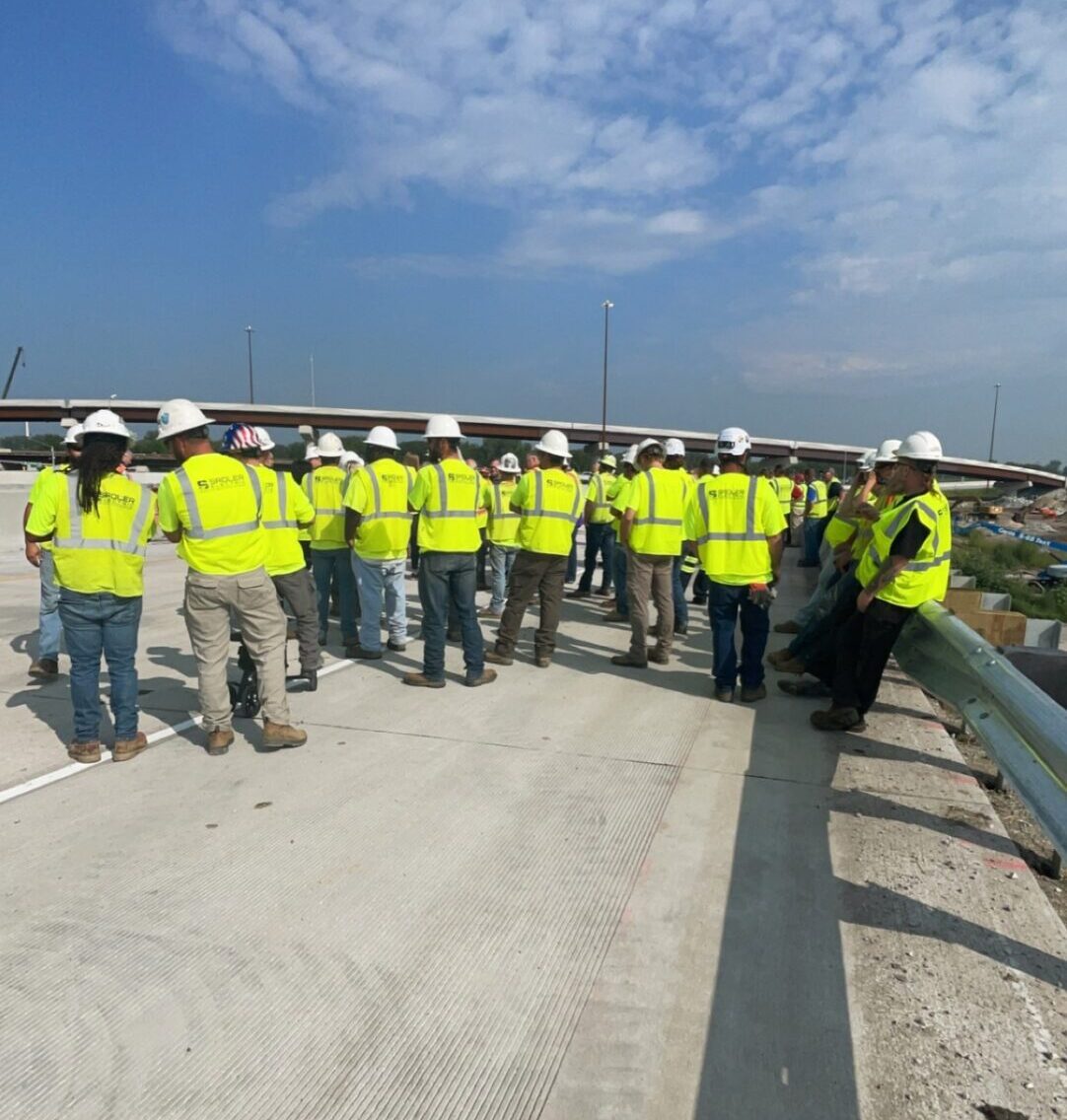
Sadler Electric installs drilled shaft foundations in the Omaha and Council Bluffs area. Call (402) 331-3217 or send us a message to talk through your project.