Drilled Shaft Installation: A Step-by-Step Process Guide for Transportation Projects
By Sadler Electric, Inc. — Omaha and Council Bluffs Infrastructure Contractors
Installing a drilled shaft foundation for a traffic signal pole or mast arm is one of the most precision-intensive steps in any signalization project. The work must meet the plan-position tolerance stated in the approved survey, structural, and agency documents. Errors made during drilling are expensive or impossible to correct after the concrete sets.
This guide walks through the installation sequence for drilled shafts used in transportation infrastructure projects — signal poles, roadway lighting, and highway sign supports — as typically performed on Nebraska DOT and Iowa DOT projects.
Step 1: Survey Layout and Utility Clearance
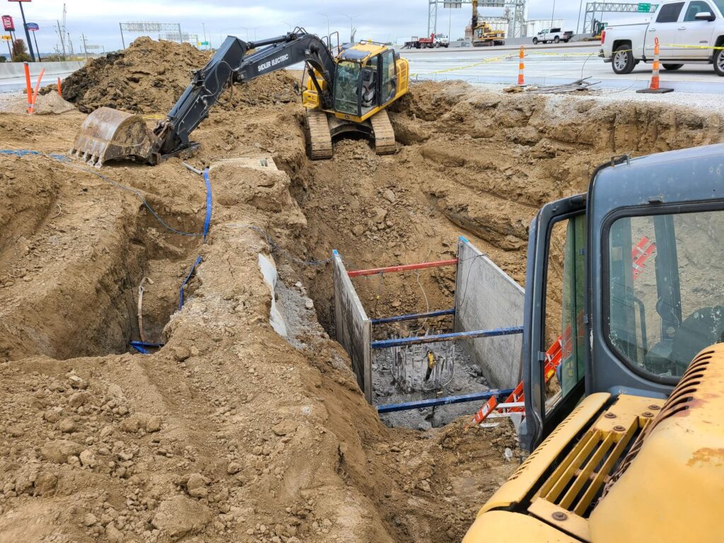
Before any drilling begins, the shaft center is staked by a licensed land surveyor to the plan coordinates. The horizontal position tolerance is the one given in the approved plans and the governing agency specification. The shaft is also laid out for rotational orientation: the anchor bolt circle on the pole base plate must face in the correct direction relative to the roadway.
Utility locating (the 811 call-before-you-dig process) is completed for all underground infrastructure near the shaft location — water, sewer, gas, electric service, fiber, and existing traffic signal conduit. Intersections in urban Omaha and Council Bluffs have dense underground utility corridors. Some contractors add ground penetrating radar scanning for complex sites as a second check.
Step 2: Equipment Mobilization and Traffic Control
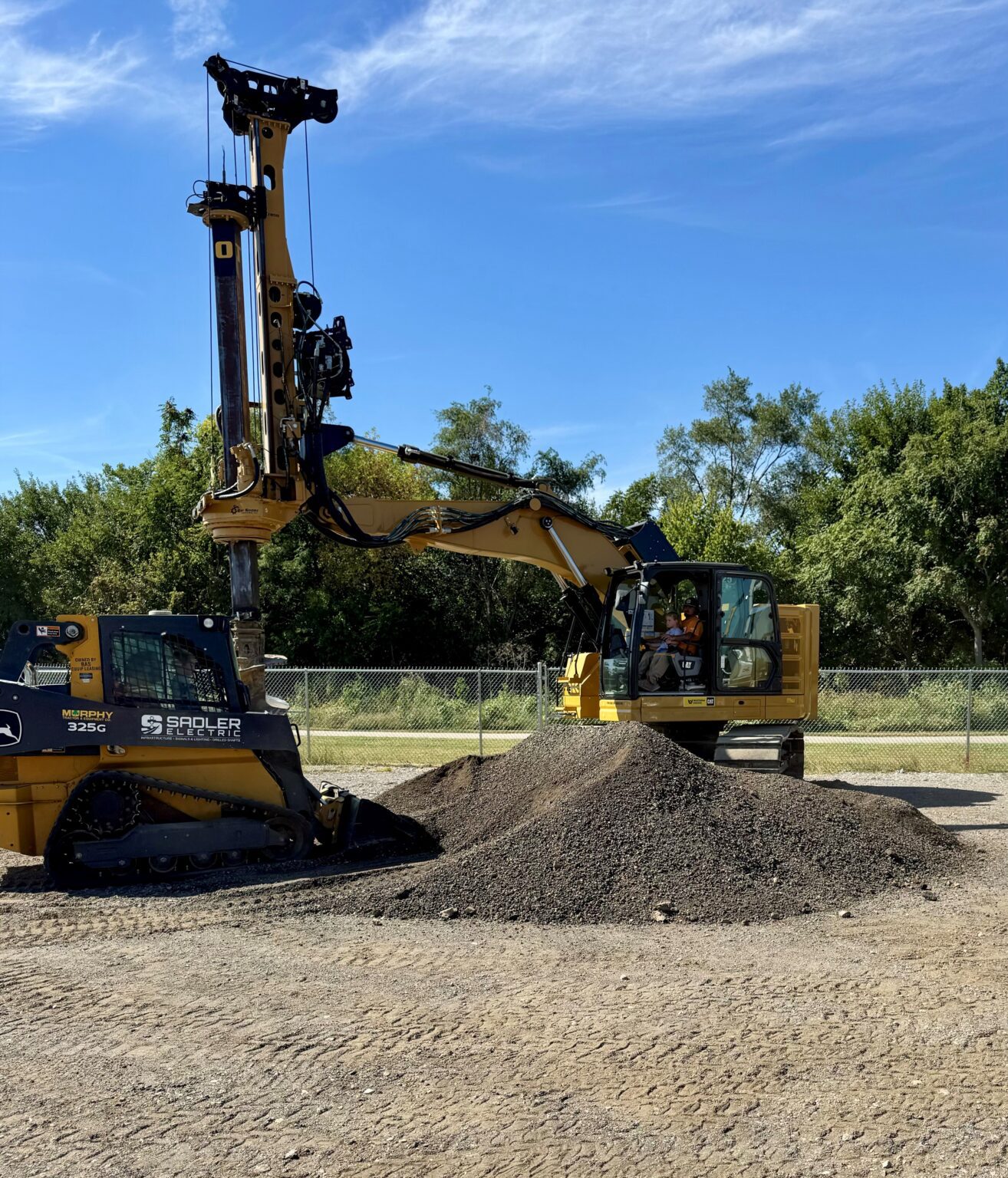
Drill rig equipment for signal and light pole foundation work ranges from compact truck-mounted units to crane-mounted Kelly bar rigs. Urban intersection work favors compact equipment that can operate within a single closed lane.
Traffic control is established per an approved traffic control plan before equipment enters the roadway. Nebraska DOT requires an approved plan and, for significant closures on state routes, a permit. Iowa DOT and the City of Council Bluffs have parallel requirements for their roadways.
Step 3: Drilling the Shaft
The drill rig advances an auger into the ground to the depth specified in the structural drawings. In the cohesive loess soils common in Douglas and Sarpy Counties, the borehole typically stands open without casing. In granular soils, saturated zones, or where groundwater is near the surface (common near the Missouri River corridor in Pottawattamie County), a temporary steel casing is advanced ahead of the auger to maintain borehole stability.
Depth is confirmed by depth counter and verified by the geotechnical inspector against the specified bearing elevation. If soil conditions differ significantly from the geotechnical report — soft zones, unexpected water, or shallow rock — the engineer of record is notified before proceeding.
Step 4: Borehole Inspection and Cleanliness
Before the reinforcing cage is placed, the borehole base is inspected. The allowable sediment, water, and base-cleanliness limits come from the governing contract specification. Iowa DOT's drilled shaft developmental specification, for instance, sets a one-half-inch sediment limit for the work it governs. Verify the Nebraska or project-specific requirement before relying on any number. A downhole camera, probe, or direct visual inspection with a light confirms base condition. If the base fails inspection, it is cleaned by cycling the auger or air-lifting the loose material before proceeding.
Step 5: Reinforcing Steel Cage Placement
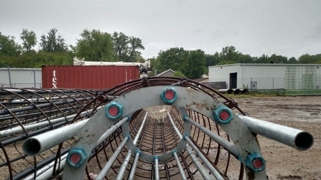
The rebar cage is pre-fabricated to the structural drawings: main bar size, spacing, and length; spiral tie or hoop size and pitch; and the elevation of the top of reinforcement. For signal pole shafts, the cage top is positioned to leave room for the anchor bolt template near the top of the shaft.
The cage is lowered concentrically into the hole by crane or rig line. Plastic or concrete spacers on the cage maintain the specified concrete cover — typically three inches — without allowing the cage to shift off center.
Step 6: Anchor Bolt Template Setting
The anchor bolt template — a steel frame holding the threaded rod bolt circle in the exact pattern matching the pole base plate — is set in position at the top of the cage before concrete placement. The template must be in the correct horizontal position, level, and oriented to the correct rotational angle for the pole to face its design direction.
Setting the anchor bolt template correctly is one of the most critical steps in the process. A bolt circle that is off-center, tilted, or facing the wrong direction cannot be corrected after the concrete sets. The fix requires coring the shaft and re-setting the bolts, which is costly and delays the pole installation.
Step 7: Concrete Placement
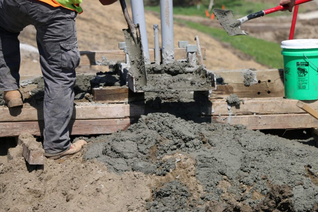
Concrete is placed by tremie pipe (when the borehole has water or slurry), or directly by pump or chute when the hole is dry and clean. Tremie placement starts at the base and works upward, displacing water and preventing contamination of the concrete column with soil or water channels.
Use the compressive-strength requirement, and the age at which it must be met, from the applicable DOT or project specification and the approved mix design. Some specifications call for self-consolidating concrete (SCC) to penetrate the rebar cage without mechanical vibration. The sampling and testing regime — which tests are run, how many cylinders are cast, and at what ages they are broken — is set by the governing specification and the project documents.
Concrete rises to the plan top-of-shaft elevation. The anchor bolt template is re-checked for position and level while the concrete is still workable.
Step 8: Temporary Casing Extraction
If a temporary casing was used, it is extracted while concrete is still fluid. Extract temporary casing under the project’s approved drilled-shaft procedure while maintaining the concrete head and placement conditions required by the governing specification. Use the engineer’s or agency’s stated embedment/control value when one is specified.
Step 9: Curing and Inspection Documentation
The shaft is protected from traffic disturbance during initial cure. In cold weather, insulating blankets or heating enclosures maintain the concrete above the minimum curing temperature required by ACI 306.
The geotechnical or construction inspector generates a drilled shaft inspection report: borehole depth and cleanliness, cage placement, anchor bolt template position, concrete volume, and mix ticket data. Submit concrete test results and inspection records as required by the contract and agency. The required test ages and submittal path must come from the project documents.
Drilled Shaft Work in Omaha and Council Bluffs
Sadler Electric, Inc. performs drilled shaft installation for traffic signal poles, mast arms, roadway lighting, and highway signing throughout the Omaha and Council Bluffs service area. The company works with Nebraska DOT, Iowa DOT, municipalities, and general contractors on drilled shaft installation for signal and infrastructure projects. The contract may require experience documentation and a project-specific drilled-shaft plan. Confirm the exact requirement in the applicable NDOT or Iowa DOT bid documents. Sadler Electric operates a fleet of five specialized drill rigs manufactured by Bay Shore Systems, ranging from the LAD140 for smaller limited-access locations and smaller-diameter shafts to the TR-60 for large production work and large-diameter shafts, along with full support equipment including cranes, telehandlers, excavators, skidsteers, slurry tanks, and mixing equipment. Contact Sadler Electric at (402) 331-3217 or sadlerelectric.com.
Specific procedures and tolerances for any drilled shaft project are governed by the applicable DOT standard specifications, contract documents, and the engineer of record. This article describes general practice.
Planning a Drilled Shaft Project?
Sadler Electric installs drilled shaft foundations in the Omaha and Council Bluffs area. Call (402) 331-3217 or send us a message to talk through your project.